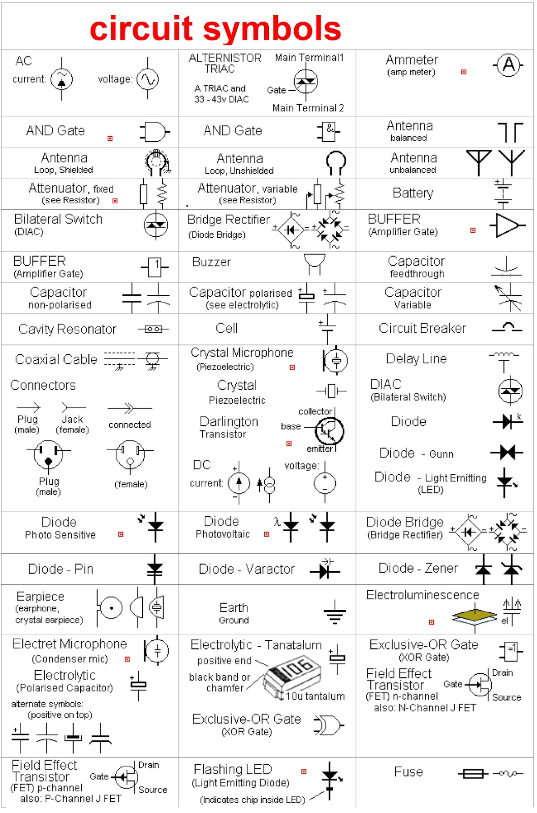
Ever looked at a circuit board or a building blueprint and felt a wave of confusion wash over you? You're not alone. These complex drawings, known as schematic diagrams, can seem intimidating at first glance. But fear not, because understanding schematic diagrams and the language of their symbols is like unlocking a secret code to the world around us. From the simplest household appliances to the most complex industrial machinery, schematic representations are essential for design, construction, and troubleshooting.
Schematic diagrams are simplified graphical representations of a system, using standard symbols to depict components and their interconnections. They strip away unnecessary visual details, focusing solely on the functional relationships within the system. Imagine trying to understand the wiring of your house by looking at the actual wires hidden within the walls. A schematic diagram provides a clear, concise roadmap, making the complex understandable.
The roots of schematic drawing can be traced back centuries, evolving alongside technological advancements. Early forms can be seen in medieval architectural plans and alchemical diagrams. The standardization of symbols emerged with the rise of electricity and the increasing complexity of circuits. Today, standardized symbolic language allows engineers and technicians worldwide to communicate effectively, regardless of language barriers.
The importance of schematic diagramming is paramount. These visual representations are the foundation for design, analysis, and communication in countless fields. They empower engineers to conceptualize and test designs before physical implementation, saving valuable time and resources. In manufacturing, schematics guide the assembly process. In troubleshooting, they provide the crucial roadmap for identifying and resolving malfunctions.
One of the main issues concerning schematic representation is ensuring accuracy and clarity. A single misplaced symbol or an unclear connection can have significant consequences. Adhering to standardization and using the correct symbols are crucial for preventing errors and misinterpretations. Therefore, consistent use of established schematic symbols is crucial for effective communication.
For example, a resistor is represented by a zigzag line, a capacitor by two parallel lines, and a transistor by a symbol resembling a sandwich. Understanding these symbols allows you to decode the function and interaction of components within a circuit. A simple schematic for a basic light circuit would show a power source, a switch, and a light bulb connected by lines representing wires.
Using schematic diagrams offers several benefits. First, they facilitate communication. A schematic diagram can convey complex information about a system quickly and efficiently. Second, they enable troubleshooting. Identifying faulty components in a system becomes significantly easier with a schematic diagram. Third, they aid in design and planning. Creating a schematic representation is the first step in developing any electrical or electronic system.
Creating a schematic diagram involves several steps. First, define the system's purpose and components. Then, select the appropriate symbols for each component. Next, draw the connections between the components, ensuring accuracy and clarity. Finally, review and refine the diagram to ensure it accurately represents the system. A successful example is a clear and accurate circuit diagram for a timer circuit used in a washing machine.
Advantages and Disadvantages of Schematic Diagrams
| Advantages | Disadvantages |
|---|---|
| Simplified representation | Oversimplification for complex systems |
| Universal understanding | Requires knowledge of symbols |
| Efficient troubleshooting | Can be time-consuming to create |
Best Practices for Implementing Schematic Diagrams: 1. Use standard symbols. 2. Maintain clarity and neatness. 3. Label components clearly. 4. Indicate signal flow. 5. Review and verify accuracy.
Real-world examples include circuit diagrams for electronic devices, piping and instrumentation diagrams (P&IDs) for industrial plants, and network diagrams for computer systems.
Challenges in schematic diagrams can include symbol confusion, complex systems, and software limitations. Solutions involve using standardized libraries, modular design approaches, and adopting advanced software tools.
FAQ: What is a schematic diagram? What are schematic symbols? Why are schematic diagrams important? How do I create a schematic diagram? What are some common schematic symbols? Where can I find resources for learning about schematic diagrams? What software can I use to create schematic diagrams? What are the different types of schematic diagrams?
Tips and tricks for working with schematic diagrams include using online symbol libraries, organizing diagrams logically, and utilizing software features like auto-routing and component libraries.
In conclusion, schematic diagrams and their associated symbols are essential tools for understanding and working with complex systems. From the initial design phase to troubleshooting and maintenance, these graphical representations provide invaluable clarity and guidance. Mastering the language of schematic symbols unlocks a deeper understanding of technology and its intricate workings. The benefits of utilizing schematic diagrams are numerous, including enhanced communication, efficient troubleshooting, and improved design processes. Embrace the power of schematics and you’ll be well-equipped to navigate the complexities of the technological world around us. Take the time to learn the fundamental symbols and explore the available resources. Start creating your own schematics, and you'll discover a powerful tool for bringing your ideas to life.
Circuit Components With Their Schematic Diagrams - The Brass Coq
schematic diagrams and their symbols - The Brass Coq
schematic diagrams and their symbols - The Brass Coq
Schematic Diagrams And Their Symbols - The Brass Coq
Symbols Used In Circuit Diagram - The Brass Coq
Circuit Components With Their Schematic Diagrams - The Brass Coq
Circuit Symbols And Diagrams - The Brass Coq
schematic diagrams and their symbols - The Brass Coq
schematic diagrams and their symbols - The Brass Coq
How To Use Schematics On Basic Electronics - The Brass Coq
Basic Circuit Schematic Symbols Voltage - The Brass Coq


