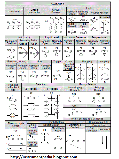
Electrical schematics are the roadmap for any electrical system. They provide a visual representation of the components and connections, allowing engineers and technicians to understand and troubleshoot circuits. A key component often found in these schematics is the relay, a versatile electromechanical switch that plays a vital role in controlling circuits. Understanding relay symbols is fundamental to interpreting and working with these diagrams effectively.
Relay diagrams depict these components using standardized symbols, which vary depending on the relay type and its specific function within the circuit. Recognizing these graphical representations is crucial for deciphering the logic and operation of a system. These symbolic representations allow for a simplified yet detailed understanding of how relays control various aspects of an electrical setup.
Historically, relays were essential for telegraphy and early telephone systems, enabling signal amplification and routing. Today, their applications are vast, ranging from industrial automation and automotive control systems to household appliances and consumer electronics. The evolution of relay graphical representation in schematics has mirrored this technological advancement, with symbols becoming more standardized and encompassing a wider variety of relay types.
The primary concern when working with relay schematics is ensuring accurate interpretation. Misunderstanding a relay symbol can lead to incorrect wiring, malfunctioning systems, and even safety hazards. Therefore, a solid grasp of relay symbols and their associated terminology is paramount. This understanding helps to avoid costly mistakes during design, installation, and maintenance.
A relay essentially consists of an electromagnet, an armature, and a set of electrical contacts. When a small current is applied to the electromagnet's coil, it creates a magnetic field that attracts the armature. This movement opens or closes the contacts, controlling a separate, often higher-power circuit. The relay symbol in a schematic represents this function, showcasing the coil and contacts in a simplified form.
Relay symbols can differ based on the type of relay. For example, a normally open (NO) contact is represented differently than a normally closed (NC) contact. Furthermore, symbols can indicate features such as latching or time-delay functions. A simple example is a relay controlling a motor. When the relay coil is energized, the NO contact closes, completing the circuit and starting the motor.
One benefit of using standardized relay symbols is clarity. They provide a concise and universally understood way to represent complex relay functions within a schematic. This clarity reduces ambiguity and improves communication among engineers and technicians. Another benefit is efficiency. Relay symbols allow for quick identification and understanding of the relay’s role in the circuit, facilitating faster troubleshooting and maintenance. Lastly, standardization promotes safety. By using recognized symbols, the risk of misinterpretation and subsequent wiring errors is significantly reduced, contributing to safer electrical systems.
Advantages and Disadvantages of Standardized Relay Symbols
| Advantages | Disadvantages |
|---|---|
| Clarity and universal understanding | Requires learning and familiarity with various symbols |
| Efficient troubleshooting and maintenance | Potential for confusion with similar symbols if not carefully studied |
| Enhanced safety through standardized representation | Variations in representation across different standards can sometimes cause ambiguity |
Best Practice 1: Always refer to a reputable standard for relay symbols. Best Practice 2: Ensure consistency in the use of symbols throughout a schematic. Best Practice 3: Clearly label all relays and associated contacts within the schematic. Best Practice 4: Use software tools that offer built-in relay symbol libraries to ensure accuracy. Best Practice 5: Double-check relay symbols and connections before implementing the design.
Frequently Asked Questions: 1. What is the difference between a NO and NC contact? 2. How is a latching relay represented? 3. What are the common applications of time-delay relays? 4. How can I identify a relay coil in a schematic? 5. What are the standard symbols for different relay types? 6. What resources can help me learn more about relay symbols? 7. What are some common troubleshooting techniques for relay-based circuits? 8. How do I choose the right relay for a specific application?
In conclusion, understanding relay symbols in electrical schematics is critical for anyone working with electrical systems. From their historical significance to their modern applications, relays play a crucial role in controlling circuits. Mastering these symbols is key to effective circuit analysis, design, troubleshooting, and maintenance, ultimately ensuring safe and efficient operation. By familiarizing yourself with standardized relay symbols and best practices, you can contribute to the successful implementation of any electrical project involving relays. Dive deeper into the world of relay schematics by exploring online resources, textbooks, and industry standards, and empower yourself with the knowledge to confidently work with these essential electrical components. This understanding not only facilitates accurate interpretation but also contributes to improved safety and efficiency in electrical system design and maintenance.
DIAGRAM Electrical Symbols For Relays Wiring Diagrams - The Brass Coq
relay circuit diagram symbols - The Brass Coq
Electrical Relay Schematic Symbols - The Brass Coq
relay symbol electrical schematic - The Brass Coq
Relay Symbol Electrical Schematic - The Brass Coq
Symbol Of Transformer In Single Line Diagram - The Brass Coq
Relay Symbol Electrical Schematic - The Brass Coq
Electrical Symbol Relay at Lee Patterson blog - The Brass Coq
Schematic Symbol Of Relay - The Brass Coq
Electrical Symbols For Schematics - The Brass Coq
Electrical Relay Symbol On Schematics - The Brass Coq
How to Read Wiring Diagrams in HVAC Systems - The Brass Coq
relay symbol electrical schematic - The Brass Coq
Schematic Symbol Of Relay - The Brass Coq
Electrical Relay Schematic Symbols - The Brass Coq


