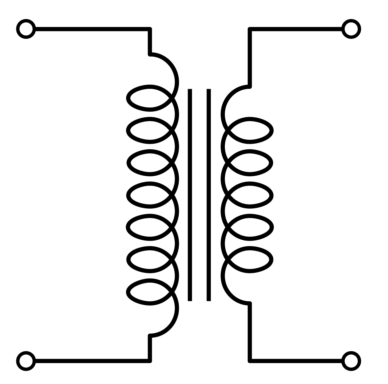
Ever peeked at a circuit diagram and felt a jolt of bewilderment at the cryptic symbols scattered across it? Like a hidden language, these symbols hold the key to understanding the electrical flow. Among these enigmatic glyphs, the transformer schematic symbol, often adorned with seemingly insignificant dots, plays a crucial role. These dots aren't random sprinkles; they signify a critical relationship between the transformer windings, dictating the direction of current and voltage.
Transformers, the unsung heroes of power distribution, alter voltage levels with remarkable efficiency. Whether stepping up voltage for long-distance transmission or stepping it down for household use, their operation hinges on the magnetic coupling between their primary and secondary windings. The dots on the transformer schematic symbol provide a visual representation of this magnetic coupling, indicating the phase relationship between the windings. Understanding these dots is essential for correctly interpreting and designing circuits involving transformers.
Historically, the standardized representation of transformers in schematics evolved with the burgeoning field of electrical engineering. As circuits grew more complex, the need for clear and concise symbolic representation became paramount. The dot convention emerged as a simple yet effective way to denote winding polarity, ensuring consistent interpretation across different designs and engineers. This standardization was instrumental in streamlining circuit design and troubleshooting, facilitating collaboration and innovation.
The importance of the transformer schematic symbol dot lies in its ability to predict the relative voltage polarity between the primary and secondary windings. This seemingly small detail impacts the overall circuit behavior, particularly when multiple transformers are interconnected. Ignoring the dot convention can lead to unintended voltage cancellations or additive effects, causing malfunctioning circuits and potentially damaging connected devices.
Misinterpreting or neglecting transformer polarity dots can lead to significant issues in circuit design and operation. For example, in audio applications, incorrect phasing can result in signal cancellation, diminishing audio quality. In power systems, polarity errors can cause dangerous voltage imbalances, leading to equipment damage or even safety hazards. Therefore, a thorough understanding of the dot convention is paramount for any engineer or technician working with transformers.
The dots on a transformer schematic indicate that the instantaneous voltage at the dotted terminals of both windings have the same polarity. This means if the voltage at the dotted terminal of the primary winding is positive, the voltage at the dotted terminal of the secondary will also be positive at that instant. Conversely, if one dotted terminal is negative, the other dotted terminal will be negative at the same instant.
A simple example is a center-tapped transformer used in a full-wave rectifier circuit. The dots on the secondary winding, coupled with the diode orientation, ensure that both halves of the AC cycle contribute to the rectified DC output, maximizing efficiency.
One benefit of correctly using dot conventions is avoiding phase cancellation in audio circuits. Another benefit is achieving the desired voltage levels in power supply designs. Finally, accurate representation using dots simplifies circuit analysis and troubleshooting.
If the dots on a transformer are not clearly marked on a schematic, consult the transformer datasheet for winding polarity information. Ensure that the schematic accurately reflects the physical transformer connections to avoid phase or voltage issues.
Challenges in interpreting transformer schematic symbol dots often arise due to inconsistencies in documentation or complex circuit layouts. Solutions include referencing reliable datasheets and using simulation software to verify circuit behavior.
Frequently Asked Questions:
1. What do the dots represent?
Answer: Winding polarity.
2. Why are dots important?
Answer: Prevent incorrect phasing and voltage issues.
3. How do dots affect audio circuits?
Answer: Proper phasing ensures correct audio signal summation.
4. How are dots relevant in power supplies?
Answer: Dots influence the output voltage level and regulation.
5. What if dots are missing from a schematic?
Answer: Consult the transformer datasheet.
6. Can dots be ignored?
Answer: No, ignoring dots can lead to circuit malfunction.
7. How to verify dot convention in a circuit?
Answer: Use simulation software or oscilloscope measurements.
8. What is the historical context of the dot convention?
Answer: Developed with the growth of complex electrical systems for clear representation.A tip for working with transformer schematic symbols is to always double-check the dot placement and its corresponding connection in the physical circuit to prevent phase-related issues.
In conclusion, the humble transformer schematic symbol dot, often overlooked, plays a vital role in circuit design. Its proper interpretation dictates the phase relationship between windings, ensuring correct voltage levels and preventing potential malfunctions. From audio applications to power systems, understanding the dot convention is paramount for engineers and technicians alike. Mastering this seemingly small detail empowers designers to harness the full potential of transformers and build reliable, efficient circuits. This understanding not only prevents costly errors but also paves the way for innovative circuit designs that push the boundaries of electrical engineering. By diligently applying the principles of transformer polarity and utilizing available resources, engineers can confidently navigate the intricate world of circuit design and ensure optimal performance and safety in their creations. Therefore, let us not underestimate the power of the dot - a small symbol with a significant impact.
Electrical Symbols For Schematics - The Brass Coq
Current Transformer Schematic Symbol - The Brass Coq
transformer schematic symbol dot - The Brass Coq
Field Coil Symbol at Ramon Shay blog - The Brass Coq
Power Transformer Schematic Symbol - The Brass Coq
Dictionary of Electronic and Engineering Transformer Terms and Definitions - The Brass Coq
Transformers Types Tutorial Circuits - The Brass Coq
Ac Wiring Diagram Symbols - The Brass Coq
Introduction to Toroidal Transformers The Talema Group - The Brass Coq
transformer schematic symbol dot - The Brass Coq
transformer schematic symbol dot - The Brass Coq
Dot Convention in Transformer - The Brass Coq
The electrical transformer is a component consisting of two or more - The Brass Coq
Transformer Circuit Diagram Symbol - The Brass Coq
Dot Convention Notation in a Transformer Phasing Polarity - The Brass Coq


