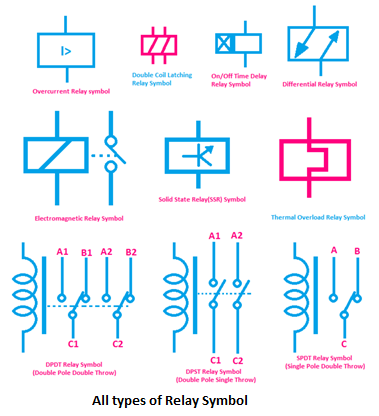
Ever peered at a circuit diagram and wondered about that curious squiggle or box labeled "K"? That’s likely the symbol for a relay, a small but mighty component that plays an oversized role in controlling electrical circuits. Understanding these symbolic representations is crucial for anyone working with electrical systems, from hobbyists to seasoned engineers. This guide will delve into the world of relay symbols, exploring their meaning, variations, and practical applications.
Relays are essentially electrically operated switches. They allow a small current to control a much larger one, enabling remote control, automation, and safety features in countless devices. Imagine wanting to turn on a powerful motor. Directly switching the high current required could be dangerous and inefficient. A relay allows a small, low-voltage signal to activate the switch, isolating the user from the high-power circuit.
The graphical representation of a relay varies depending on the type and specific application. While there isn’t one universally standardized symbol, common depictions involve a coil and a set of contacts. The coil represents the electromagnet, and the contacts represent the switched circuits. Variations might include normally open (NO) or normally closed (NC) contacts, indicated by different line connections to the contact symbols. Recognizing these subtle differences is key to correctly interpreting circuit diagrams.
The history of relay symbols is intertwined with the development of electrical engineering itself. As circuits became more complex, the need for standardized representations grew. Early diagrams often used simplified drawings of the physical relay, evolving over time into more abstract and schematic forms. Understanding the evolution of these symbols provides context for their modern usage and emphasizes the importance of clear communication in technical drawings.
Misinterpreting a relay symbol can lead to faulty circuit design, malfunctioning equipment, and even safety hazards. Imagine wiring a safety system based on a misinterpreted normally closed symbol. Instead of providing protection, the system could fail to activate in an emergency. Therefore, a thorough understanding of relay symbology is crucial for ensuring the safe and reliable operation of electrical systems.
Relay symbols are essential for efficient and accurate circuit design, allowing engineers to communicate complex systems in a concise and standardized way. Relays themselves enable complex automation and control systems, from simple household appliances to sophisticated industrial machinery.
One benefit of understanding relay symbols is the ability to troubleshoot electrical systems effectively. By tracing the connections and interpreting the symbols, one can pinpoint potential issues and repair malfunctions more efficiently. Another benefit is the improved design of electrical systems. Clear and accurate symbols facilitate the creation of efficient and reliable circuits, reducing the risk of errors and improving overall performance. Finally, a strong grasp of relay symbology enhances communication between engineers and technicians. A common language of symbols ensures that everyone involved understands the circuit's functionality and operation.
Advantages and Disadvantages of Using Relays
| Advantages | Disadvantages |
|---|---|
| Electrical Isolation | Slower switching speeds compared to solid-state devices |
| Ability to switch high currents with low control currents | Physical contacts can wear out over time |
| Relatively inexpensive | Can generate audible clicks during operation |
Five best practices for implementing relays include choosing the right relay for the application, ensuring proper contact ratings, providing adequate suppression for inductive loads, using appropriate wiring techniques, and regularly inspecting and maintaining relay contacts.
Challenges related to using relays might involve contact bounce, arcing, and contact wear. Solutions include using debouncing circuits, arc suppression techniques, and choosing relays with appropriate contact materials and ratings.
Frequently asked questions about relays often revolve around contact ratings, coil voltage, switching speed, and appropriate applications. Understanding these fundamental aspects is crucial for selecting and using relays effectively.
In conclusion, understanding relay symbols is essential for anyone working with electrical circuits. These small but significant symbols represent a crucial component that enables complex control and automation systems. From designing circuits to troubleshooting malfunctions, a solid grasp of relay symbology is invaluable. Learning to interpret these graphical representations unlocks the power of relays, allowing us to build more efficient, reliable, and safe electrical systems.
relay circuit diagram symbols - The Brass Coq
symbol for a relay - The Brass Coq
Circuit Diagram Relay Symbol - The Brass Coq
symbol for a relay - The Brass Coq
Solid State Relay Schematic Symbol - The Brass Coq
Relay Logic Diagram Switch Symbols - The Brass Coq
symbol for a relay - The Brass Coq
Timer Relay Schematic Symbol - The Brass Coq
Overload Relay Wiring For Contactor And Overload Wiring Diagr Word - The Brass Coq
Schematic Symbol Of Relay - The Brass Coq
Electrical Relay Symbol On Schematics - The Brass Coq
Relay Wiring Diagram Symbols - The Brass Coq
Electrical Relay Symbol On Schematics - The Brass Coq
symbol for a relay - The Brass Coq
Electrical Schematic Relay Symbol - The Brass Coq


